Packing & Expanding Polygons : An ongoing exploration
I've been packing lots of irregular polygons into the canvas, and discovered some interesting (and some annoying) geometry along the way.
Collisions 101
I started out detecting collisions in the same way as in my project Maplands, which you can read about in detail here.
Here’s how the collision checking worked:
Create a potential new polygon, with a path of points as the outline.
Check distances from each new point to all the points in existing polygons.
If any points are too close, discard that new polygon and try again.
This method is really checking for collisions on the paths, which means that smaller shapes can appear inside larger ones

Looks kind of cool, but I wanted to have the option to exclude those kinds of collisions as well.
Proper polygon packing
I need to check if any point of the new polygon is inside an existing polygon instead.
I wrote a twitter thread about that last month, after it came up in a different project. I subsequently discovered that there is a built in canvas function, isPointInPath(); which enables us to check this this easily.
Here it is, working perfectly:

spacing
Okay, but those shapes are very tightly packed - what if I want a gap between them?
With the original point checking method, we just increase the minimum distance allowed between points. With the isPointInPath method, we can implement spacing by creating a larger path around each polygon, and checking if the new points are inside that one.
Sounds simple, right? Surely all I need to do is find the centre of the polygon and move every point outwards.
Well, here's how that looks.

Oh no. Turns out this is a whole thing.
The problem is - if you think about the orientation of each edge of the polygon, edges which are perpendicular to the outward expansion have a nice border, but edges which are parallel to it have moved in the wrong direction and we get a small or non-existent border.
Creating outer borders Around a Polygon
Luckily I’m not the first person to encounter this problem. The clearest example I found of the (partial) solution was in this codepen, which I dug into and repurposed.
Here's how it works:
Create an edge between each point and the next one
Move each edge outwards at the angle perpendicular to the edge
That first stage gets us to this:

Then we can start creating the actual outer path:
Check if each edge intersects with the next one
If it does, this is an inny bit - add a point to the outer path at the intersection location
If it doesn’t, this is a pointy bit - create an arc of points around the original point.
That gives us this:

Success!
Well, kind of. Remember when I said it was a partial solution?
Sneaky edge cases
When the size of the expansion is large relative to the distance between the points in the polygon, we can get weird results:

These loops don’t actually cause a problem for collision checking, because isPointInPath() can still return true inside the loops (you can toggle whether it does or not, with the fillRule parameter)
So I am able to pack polygons in to the canvas like this:


Hurray!
The Problem
Later though, I decided it could be nice to try actually drawing the borders as well, so I needed to fix the loop issue.
If we look at this problematic polygon, and its extruded paths, we can start to get an idea of the bad thing that’s happening.


Looking more closely at the area with the loop, let’s isolate the two particular edges in question. I’ve also colour coded the corresponding edges on the original polygon, so you can see where the extruded edges came from.

Think back to the method for creating the outer path. We check each extruded edge to see if it intersects with the next one and:
If it does, this is an inny bit - add a point to the outer path at the intersection location
If it doesn’t, this is a pointy bit - create an arc of points around the original point.
The border here is so large that the edges have gone past each other, causing the algorithm to think it is a pointy bit and attempt to create an arc around it. Since this vertex is pointing inwards, it does this in the “wrong” direction, and we get the weird internal loop. Nightmare.
A Fix?
The first part of the problem is that we are misidentifying that vertex as pointing out instead of in, because the edges do not intersect. It’s pretty easy to compare the angles of the two edges around the vertex to figure out which way it’s pointing instead. I swapped in that method.
Now that we’re correctly identifying this as an inny bit, we still need to know where to place a vertex on the border path.
To do this, we can lengthen the extruded edges, so that they do intersect (first image below), and then create a vertex in the border path there (second image)


That’s getting kind of close, but something weird is going on.
In the next image I’ve added colour coded dots to each of the points in the border path.
Light blue dots are points created as an arc around an outie vertex.
Dark blue dots are points at an intersection for an innie vertex.

The intersection point for that innie vertex is in the middle of the arc around the next vertex, meaning that the path goes back and forth.
A fix for the fix
Let’s look more closely at how the arcs are created, and see if we can fix this.
In the first image below, we see the extruded edges around the pointy vertex.
In the second image, an arc of points has been added, joining up the ends of the extruded edges. Every arc has 5 points, evenly spaced through the range of angles between a start and end angle (marked by thin white lines and defined by the ends of the extruded edges).


The issue occurs because the intersection point from the adjacent vertex appears within this vertex’s angle range (first image below)
To fix this, whenever we create an arc of points, we’ll look at the adjacent vertices and, if they are innies, we’ll adjust the start and end angles we use to create the arc (second image below)
The dark blue dot is in the same place in both images, but the light blue dots are closer together in the second image.


Here’s our new border -


More vertices, more problems
As the borders get larger or the number of points gets higher, we encounter more problematic edge cases. Sometimes the arcs of two pointy vertices near each other can also overlap, creating an awkward shape.

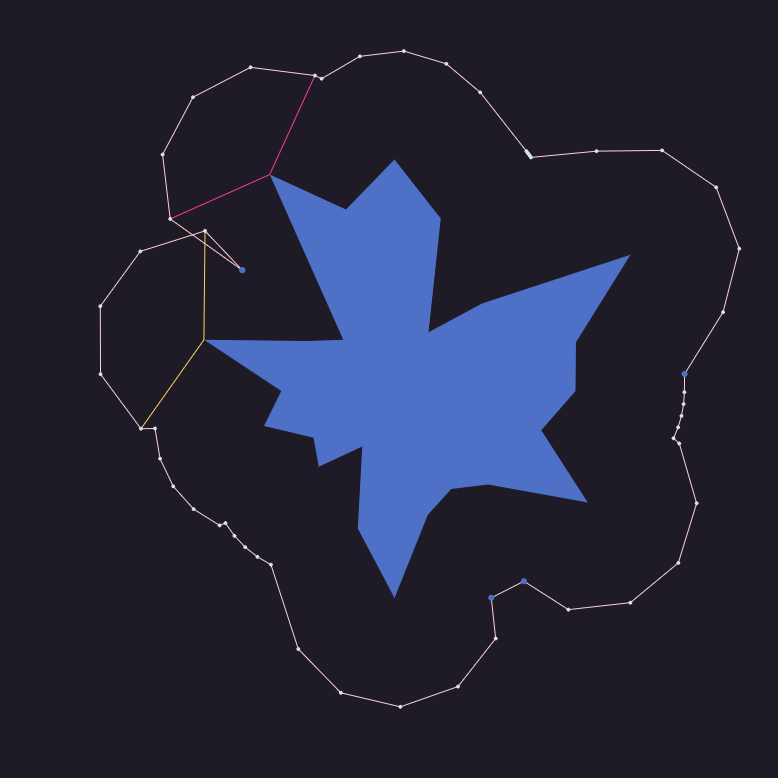
To account for this, I now have each outward pointing vertex find the next outward pointing vertex along the path in each direction and look at the outer angles of its arc points, from a midpoint between them. If there is overlap, the arc is adjusted, and we also delete the innie vertex points in between, giving us this:


In the second image above, the pink arc is the same as the one before, while the yellow one has had one point removed and the dark blue point from the inner vertex has also been removed.
It would be better to recalculate the yellow arc with new angles rather than deleting its points, but I haven’t implemented that (yet?).
It’s problems all the way down
This algorithm is certainly still not perfect. In the image below you can see how a very pointy polygon still creates problems, because arcs from several vertices away are overlapping with one another.
Instead of just checking the neighbouring vertexes, we really need to iteratively check polygons further and further along the path until we find ones that don’t overlap. This is another thing I haven’t (yet?) implemented.

A hacky fix
I did find a pretty fun fix along the way!
Notice how most of the problems are caused by bits of the path going inwards where they shouldn’t?
Well, I had the idea to do the following:
Create an extra version of the border path, about half a pixel inside the main border path.
Check every point on the outer path against the inner one, deleting any points that are inside it.
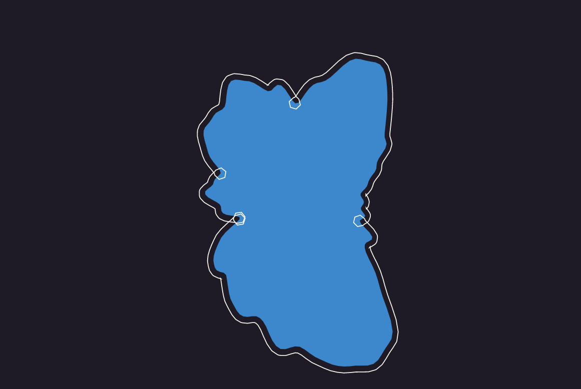
Let’s wind back a few fixes, and find a problematic polygon:

Here’s a depiction of the two paths. I’ve exaggerated the gap between them a bit, so you can see more clearly. The yellow one is the main path and the pink one is the inner path.


And then, if I go through the yellow path and use isPointInPath to deleted any points that are inside the pink one, we get this border:

Conclusion
The hacky fix is interesting because, for any technical implementation it would not be sufficient… but for aesthetics it’s completely legit! Kind of cool how that idea would be unlikely to come up in any other field.
Using a combination of these techniques (as well as a few others I didn’t have time to write about!), I’m now getting outputs like these:


This is an ongoing project, with a few more bugs to fix, and more features to add in… and it’ll be coming to fxhash as soon as it’s ready!